Prices incl. GST
Out of Stock.
- Product Code: MIKROE-2479
- MPN: MIKROE-2479
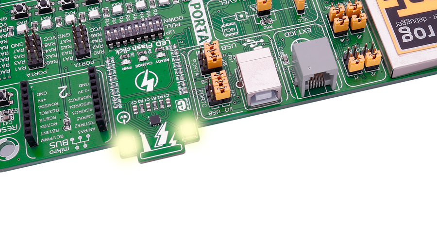
LED Flash click functions as a high power LED flash, and carries the CAT3224 flash LED driver. The click is designed to run on a 5V power supply. It communicates with the target microcontroller over the following pins on the mikroBUS™ line: AN, RST, PWM, and INT.
Note: Please be careful - do not look into the LEDs while they are on, it may be harmful to your eyesight.

CAT3224 features
The CAT3224 is a very high−current integrated flash LED driver which also supports the charging function for a dual−cell supercapacitor applications. Ideal for Li−ion battery−powered systems, it delivers up to 4A LED flash pulses, far beyond the peak current capability of the battery.
Dual−mode 1x/2x charge pump charges the stacked supercapacitor to a nominal voltage of 5.4 V, while an active balance control circuit ensures that both capacitor cell voltages remain matched.
The driver also features two matched current sources. External resistors provide the adjustment for the maximum flash mode current (up to 4 A) and the torch mode current (up to 400 mA). A built−in safety timer automatically terminates the flash pulse beyond a maximum duration of 300 ms.
The CAT3224 has a shutdown mode that is so low that ON Semiconductor can safely call it "zero" mode. In this mode, it typically uses only 1μA.
Information about the LED indicators
On the LED Flash click there are three different LED indicators, here is how they operate:
CHARGE — When this LED is on the driver is in charge mode.
READY — When this LED is on it indicates that the supercapacitor is fully charged.
PWR — Indicates if power is present.
Additional information about the pins
FLAG is an active−low open−drain output that notifies the microcontroller that the supercapacitor is fully charged by pulling the output low (pin 15 in the mikroBUS). When using FLAG, this pin should be connected to a positive rail via an external pull−up resistor.
TORCH is the torch mode enable pin. When high, the LED current sources are enabled in torch mode.
FLASH is the flash mode enable pin. When high, the LED current sources are enabled in flash mode. If FLASH is kept high for longer than 300 ms typical, the LED channels are automatically disabled.
LEDA, LEDB are connected internally to the current sources and must be connected to the LED anodes. Each output is independently current regulated. These pins enter a high−impedance ‘zero’ current state whenever the device is placed in shutdown mode or FLASH and TORCH are low.
Specifications
| Type | LED Segment |
| Applications | Applications that require a high power LED flash |
| On-board modules | CAT3224 flash LED driver |
| Key Benefits | Flash mode and Torch mode |
| Interface | GPIO |
| Input Voltage | 5V,5V |
| Click board size | M (42.9 x 25.4 mm) |
Pinout diagram
This table shows how the pinout on LED Flash click corresponds to the pinout on the mikroBUS™ socket (the latter shown in the two middle columns).
Programming
Code examples for LED Flash click, written for MikroElektronika hardware and compilers are available on Libstock.
Code snippet
The demo is realised as FSM (Finite State Machine). It has four states for contolling output signals (TORCH, FLASH, CHRG).
The demo starts in charge state which enables charge mode. It waits for FLAG signal (active low) from LED driver to switch to ready state. When in ready state, user can press specified button to drive LEDs in flash mode, burst current for short duration of time. After flash state is over (300 ms), it returns to charge state. User, aslo can press specified button to switch between torch or flash states. When in torch state, the program puts LED driver in torch mode, which allows the LEDs to run for extended time.
01 void main()
02 {
03     MCU_Init();
04
05     state = STATE_CHARGE;
06     next_state = STATE_CHARGE;
07
08     while(1)
09     {
10         switch(state)
11         {
12             case STATE_CHARGE:
13                 Write_Mode_Text(1, CL_GRAY, 1, CL_BLACK, 1, CL_GRAY);
14                 TORCH = 0;
15                 FLASH = 0;
16                 CHRG  = 1;
17
18                 if(!FLAG)
19                     next_state = STATE_READY;
20
21                 if(Button_Pressed(&GPIO_PORT_64_66, 0, &buttonstate_up))
22                     next_state = STATE_TORCH;
23
24                 break;
25
26             case STATE_READY:
27                 Write_Mode_Text(0, 0, 0, 0, 1, CL_BLACK);
28                 if(Button_Pressed(&GPIO_PORT_64_66, 1, &buttonstate_center))
29                     next_state = STATE_FLASH;
30
31                 if(Button_Pressed(&GPIO_PORT_64_66, 0, &buttonstate_up))
32                     next_state = STATE_TORCH;
33
34                 break;
35
36             case STATE_FLASH:
37                 Write_Mode_Text(0, 0, 0, 0, 1, CL_GRAY);
38                 CHRG = 0;
39
40                 FLASH = 1;
41                 Delay_ms(300);
42                 FLASH = 0;
43
44                 next_state = STATE_CHARGE;
45                 break;
46
47             case STATE_TORCH:
48                 Write_Mode_Text(1, CL_BLACK, 1, CL_GRAY, 1, CL_GRAY);
49                 TORCH = 1;
50                 FLASH = 0;
51                 CHRG  = 0;
52
53                 if(Button_Pressed(&GPIO_PORT_64_66, 0, &buttonstate_up))
54                     next_state = STATE_CHARGE;
55
56                 break;
57         }
58
59         state = next_state;
60         Delay_ms(POLLING_PERIOD);
61     }
62 }


